
Description
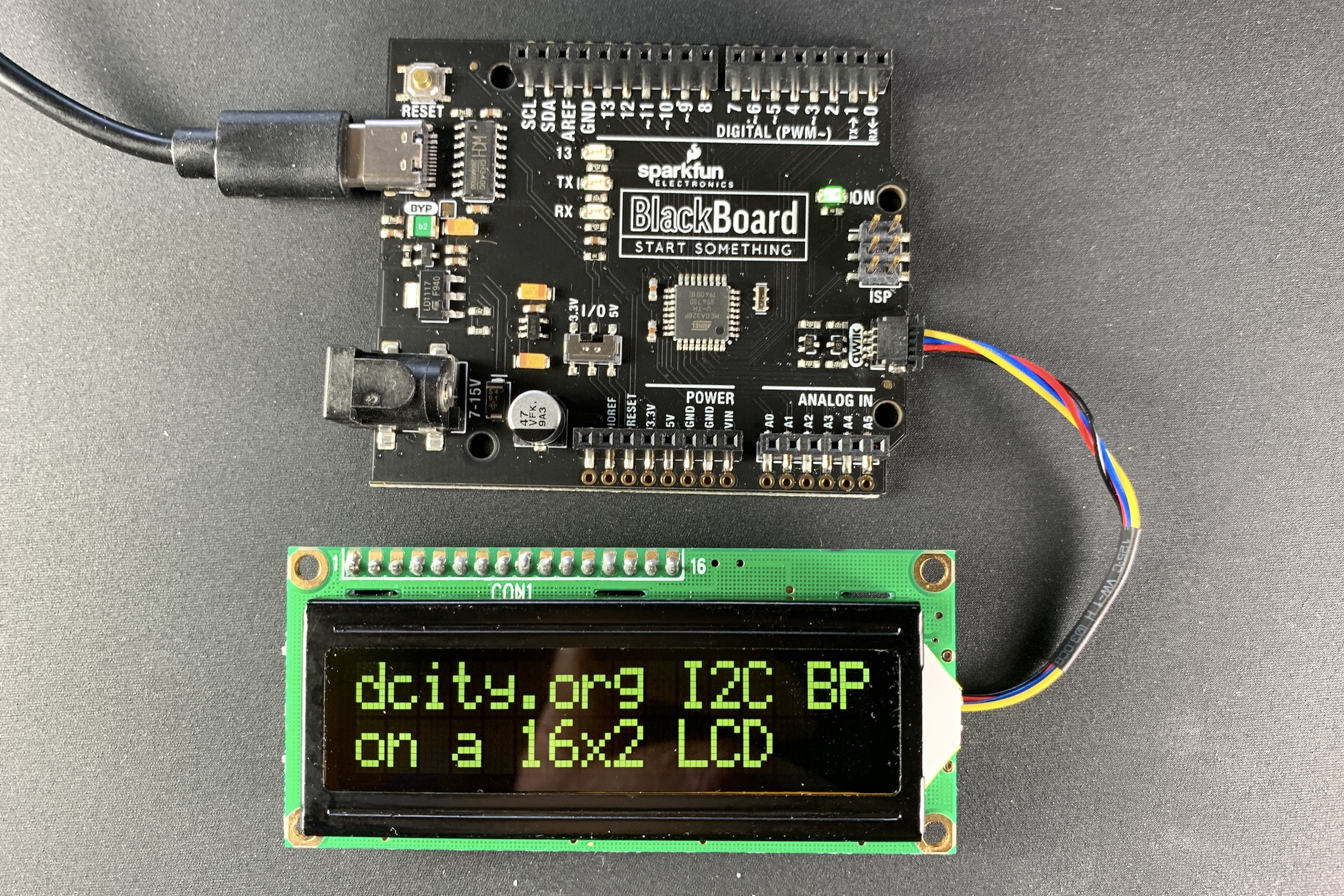
This project is a backpack board that sits on the back of many common LCD character displays (16×1, 16×2, 20×2, 20×4, etc.), and it interfaces the display to the I²C bus for easy connection to many microcontrollers. A software library is available that works with Arduino, Particle and Raspberry Pi boards.
LCD character modules are widely available and are very reasonably priced. They come in many different sizes (16×1, 16×2, 20×2, 20×4, etc.) and in many different colors. Nearly all electronic suppliers sell them, and you can even get them on Amazon and eBay.
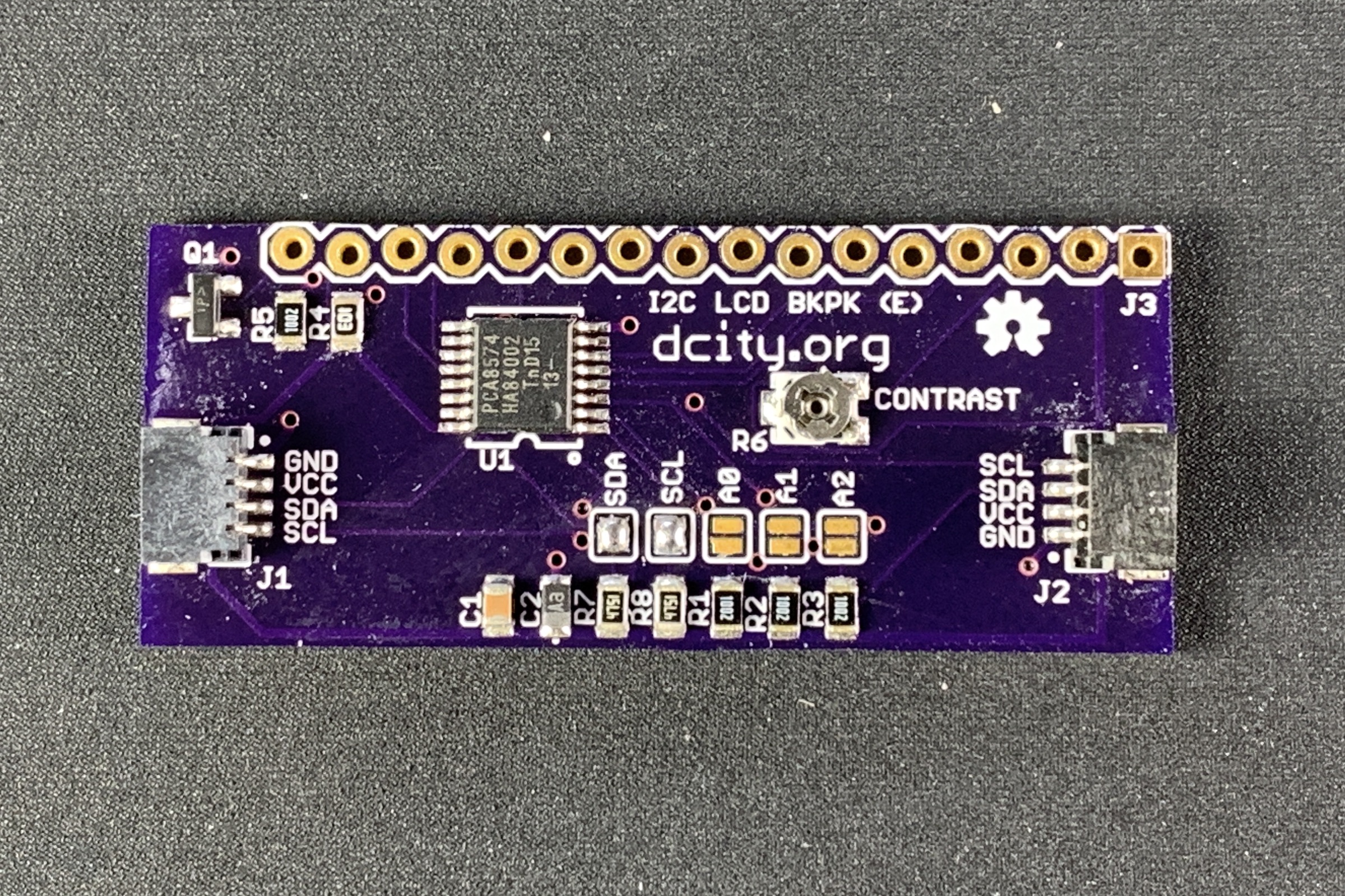
These LCDs typically require a lot of pins from the microcontroller to operate, but this project converts the displays to operate with the two pin I²C interface. This project consists of a board that sits on the back of the display, and provides two Qwiic type I²C connectors for easy connection to a microcontroller. This board also has the I²C pullup resistors (enabled with solder jumpers) and jumpers to select the I²C address. LCDs are available in either 3.3 or 5 volts, and this backpack board will work with either type.
This backpack board requires that you use a character LCD module that has the HD44780 controller chip, which almost all low cost character LCD modules do use. The display can have from 1 to 4 rows of up to 24 characters in each row.
Note: This backpack board is for use with LCD “character” modules, and not “graphic” modules.
I²C LCD Backpack “bare” pc boards are available from OSH Park.
To make it easy to use this display, I wrote software libraries for the Arduino, Particle and Raspberry Pi microcontrollers. In this library there are over 20 functions, such as clear(), moveCursor(), createChar() (for making custom characters), and write() (for using the Print function).
Files
The schematic and pcb layout files (Eagle and pdf) are available at this Github repository.
Parts
This project does not require many parts, and most are available from Mouser. Bare PC Boards are available from OSH Park.
| Qty | Part | Value | Package | Vendor | Part Number |
|---|---|---|---|---|---|
| 1 | C1 | .1uF | 0805 | Mouser.com | 80-C0805C104M5R |
| 1 | C2 | 10uF | 0805 | Mouser.com | 647-F921A106MPA |
| 2 | J1,J2 | 4 pin | smd Qwiic connector | mouser.com | 485-4208 |
| 1 | J3 | 16 pins | .1 Header Pins | Mouser.com | 855-M20-9991645 |
| 1 | Q1 | 2222A Transistor | SOT23-3 | Mouser.com | 863-MMBT2222ALT1G |
| 5 | R1-5 | 10K | 0805 | Mouser.com | 71-CRCW0805-10K-E3 |
| 1 | R6 | 10K pot | TC33X | Mouser.com | 652-TC33X-2-103E |
| 2 | R7,R8 | 4.75K | 0805 | Mouser.com | 71-CRCW0805-4.75K-E3 |
| 1 | U1 | PCA8574 | TSSOP16 | Mouser.com | 771-PCA85PW118 |
| 1 | PC Board | OSH Park | Order Link |
You can purchase LCD modules from many sources including Amazon and eBay. The LCD displays MUST have the HD44780 controller chip (almost all character LCD modules use this controller, but verify this to make sure).
I²C LCD Backpack “bare” pc boards are available from OSH Park.
Assembly
As you probably noticed, this board uses surface mount components, so you will need some skill in dealing with these small parts. Sparkfun has an excellent series of tutorials if you want to brush up your knowledge on soldering these small parts..
Hookup
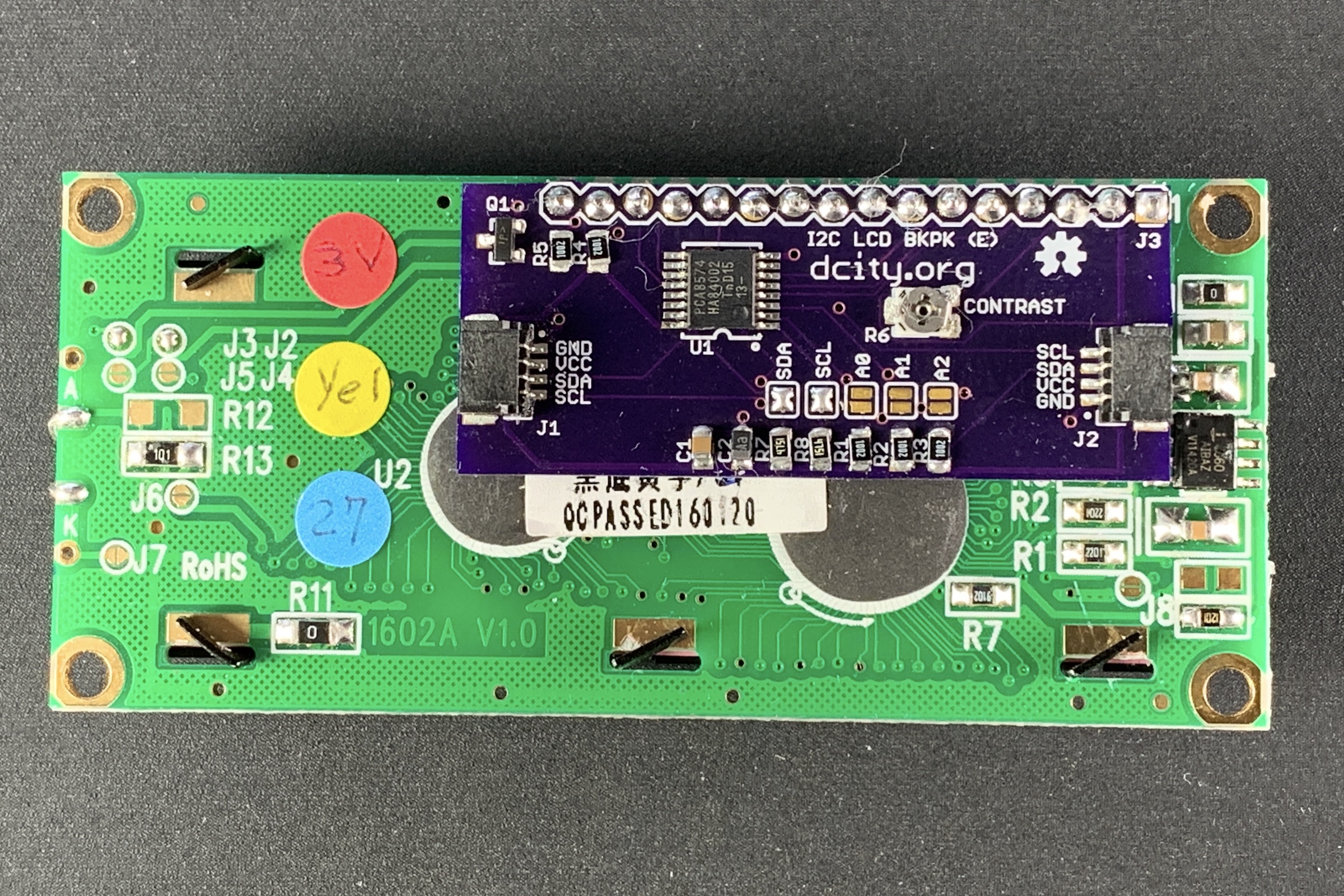
Solder the backpack board to the LCD module using a 16 pin strip header (.1 inch pin spacing).
Using a 4 pin Qwiic type cable, attach the backpack board to a microcontroller that has a I²C Qwiic type connector on it. This will power the display and connect the SDA and SCL lines to the microcontroller.
When you first power up the display and run some software that outputs characters you may not see anything on the display. There is a contrast adjustment pot (R6) that you can adjust with a very small screwdriver. Adjust the pot until you see the best contrast and viewing angle for your application.
Jumpers
There are five solder jumpers near the center of the backpack board. To “close” a jumper, carefully solder a bridge across the two pads using a small amount of solder.
SJ1, SJ2, and SJ3 control the I²C address of the board. The following table shows the possible address combinations.
| SJ3 | SJ2 | SJ1 | I²C address |
|---|---|---|---|
| closed | closed | closed | 40 hex |
| closed | closed | open | 41 hex |
| closed | open | closed | 42 hex |
| closed | open | open | 43 hex |
| open | closed | closed | 44 hex |
| open | closed | open | 45 hex |
| open | open | closed | 46 hex |
| open | open | open | 47 hex |
If you solder across SJ4 and SJ5 you can enable pull up resistors on the signals SDA and SCL (respectively). At least one pull up resistor is required on these lines somewhere on your various hardware boards.
Software
For Arduino, Particle and Raspberry Pi users, the I2cCharDisplay library provides functions the take advantage of the features of this display. An included demo program shows the usage of the functions. These links give the details.
- Information on using the Library
- Github repository for the Arduino software library
- Github repository for the Particle software library
- Github repository for the Raspberry Pi software library
Miscellaneous
Qwiic cables in various lengths are available from Adafruit, Sparkfun, Mouser, Digikey and Amazon.
License Information
Our License Information is here.
Leave a Reply