
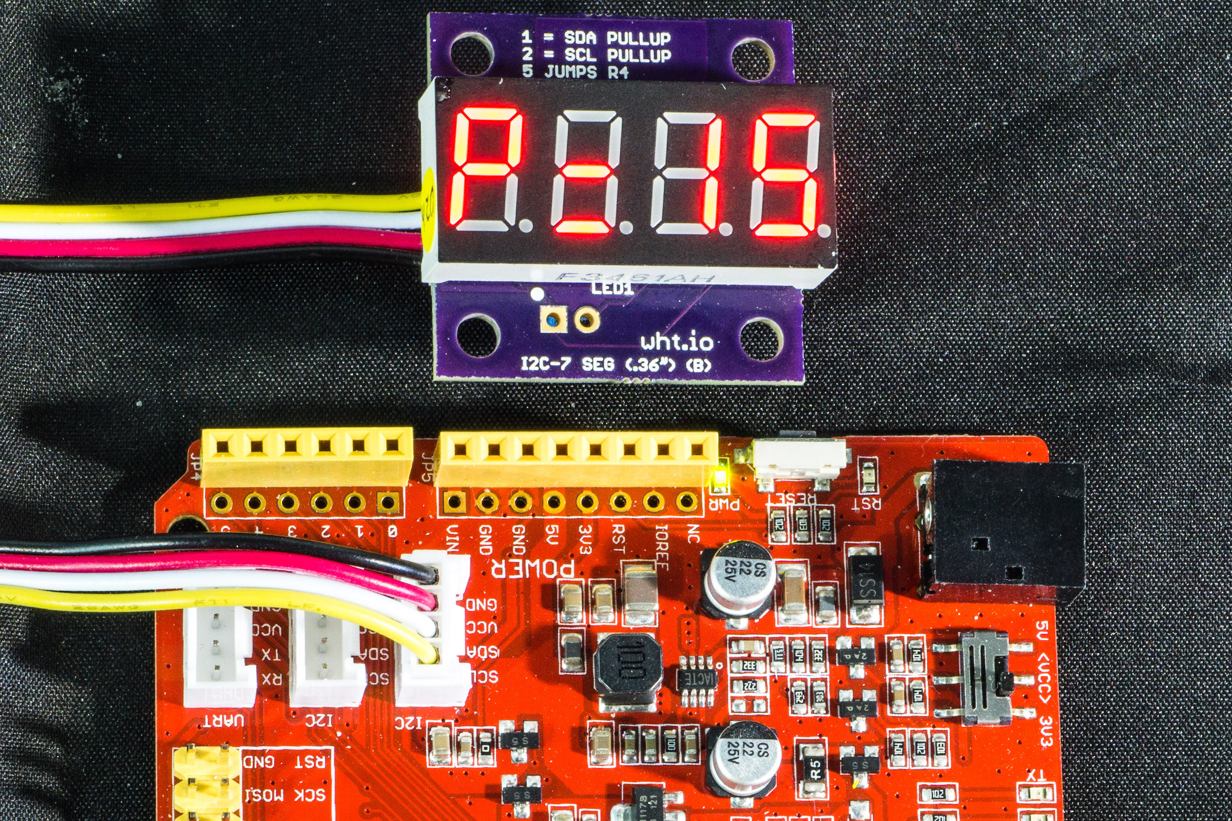
Note: The pictures show the backpack board with Grove type connectors, but they have been changed to Qwiic connectors.
Description
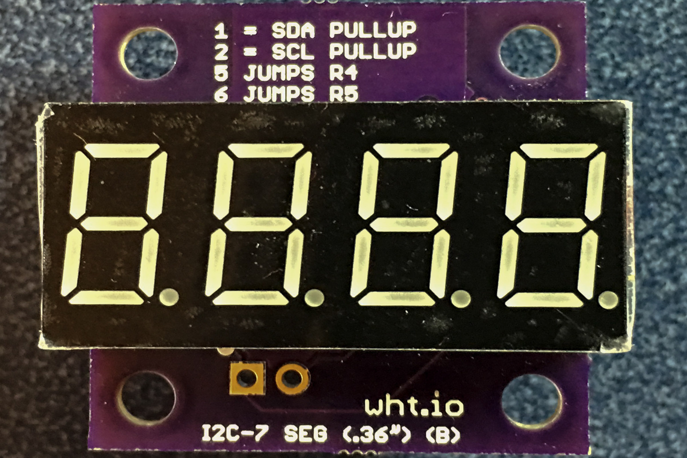
This project is a backpack board that sits on the back of four digit 7 segment LEDs (.36 inches tall), and it interfaces the LED to the I²C bus for easy connection to many microcontrollers. A software library is available that works with Arduino, Particle and Raspberry Pi boards.
LEDs are inexpensive and provide a great way to display information from microcontrollers. This project provides the details for making a 4 digit 7 segment LED module using LEDs that have a height of 0.8 inches (see my other projects for other sizes). To make the module easy to use with Arduino, Particle and Raspberry Pi boards, software libraries are available for these microcontrollers.
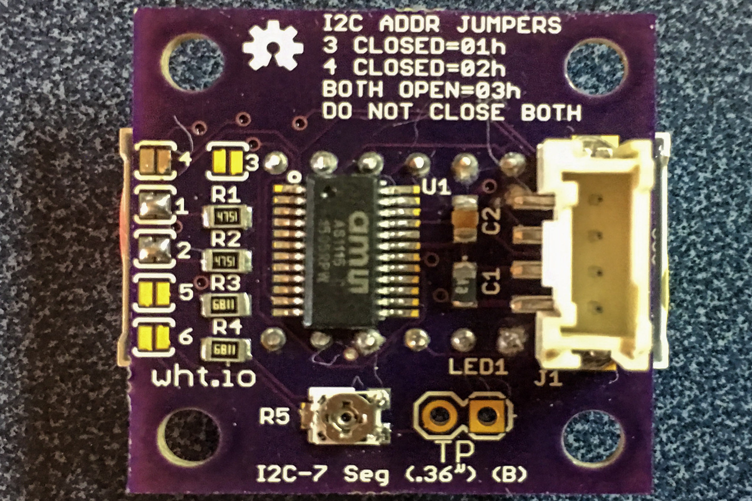
This design uses the AMS AS1115 LED controller chip (datasheet). Only two pins are used to communicate between the microcontroller and the LED module (using the I²C interface). The board has I²C pullup resistors (enabled with solder jumpers) and jumpers to select the I²C address. The module will operate with either 3.3 volts or 5 volts and a pot is used to easily adjust the brightness of the LED (and your software can also control the brightness).
I²C 7 Segment LED Backpack “bare” pc boards are available from OSH Park.
To make it easy to use this LED display, I wrote software libraries for the Arduino, Particle and Raspberry Pi boards. The library consists of 12 functions, such as clear(), moveCursor(), and write() (for displaying ASCII characters).
Files
The schematic and pcb layout files (Eagle and pdf) are available at this Github repository.
Parts
This project does not require many parts, and most are available from Mouser. Bare PC Boards are available from OSH Park.
| Qty | Part | Value | Package | Vendor | Part Number |
|---|---|---|---|---|---|
| 1 | C1 | 10uF | 0805 | Mouser.com | 647-F921A106MPA |
| 1 | C2 | .1uF | 0805 | Mouser.com | 80-C0805C104M5R |
| 2 | J1,J2 | 4 pin | smd Qwiic connector | mouser.com | 485-4208 |
| 2 | R1,R2 | 4.75K | 0805 | Mouser.com | 71-CRCW0805-4.75K-E3 |
| 2 | R3,R4 | 10K | 0805 | Mouser.com | 71-CRCW0805-6.81K-E3 |
| 1 | R5 | 50K pot | TC33X | Mouser.com | 652-TC33X-2-503E |
| 1 | U1 | AS1115 | QSOP24 | Mouser.com | 985-AS1115-BSST |
| 1 | PC Board | OSH Park | Order Link | ||
| 1 | LED1 | .36″ tall LED | 12 pin | see table below | see table below |
The LEDs must be common cathode. The following chart shows some LEDs that are available. There are many others available on eBay, Digikey, and Mouser.
| Vendor | Color |
|---|---|
| Amazon | Red |
| eBay | Red |
| AliExpress | Red |
I²C 7 Segment LED Backpack “bare” pc boards are available from OSH Park.
Assembly
As you probably noticed, this board uses surface mount components, so you will need some skill in dealing with these small parts. Sparkfun has an excellent series of tutorials if you want to brush up your knowledge on soldering these small parts.
A Qwiic type connector can be installed in positions J1 and J2. Since the board is so small, I was not able fit another connector type.
IMPORTANT: Install the LED to the NON-COMPONENT side of the board and solder the leads on the COMPONENT side. The decimal points on the LED should be closest to pin 1 (square pad) on the board.
Hookup
Using a 4 pin Qwiic type cable, attach the LED backpack board to a microcontroller that has a I²C Qwiic type connector on it. This will power the display and connect the SDA and SCL lines to the microcontroller. If you are using the 4 pin header connecter instead, follow the pin legend on the board to make the I2C and power connections to your microcontroller. See below for information about Qwiic cables that are available.
Current Setting Resistance
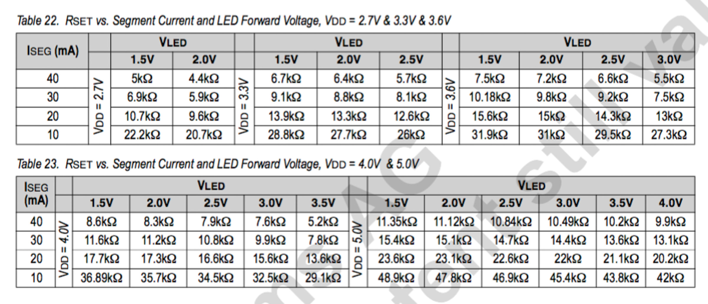
The board has two resistors and a pot (R3,R4,R5) to limit the amount of current that is fed to the LED segments. The LEDs have two specifications that should not be exceeded in order to protect the LED. Look the the data sheet for the LED you are using and find the forward voltage (typically around 2.0 volts) and the typical segment current for the LED (typically 10-20mA). Using the chart below (and the supply voltage that you are using for the board, 3.3 or 5 volts) find the value of RSET. For example, if your supply voltage is 5.0 volts, LED segment current is 20mA, and the LED forward voltage is 2.0 volts, then the value of RSET (from the table) is 23.1 k ohms. This table is from the AS1115 datasheet
To set this resistance on the board, disconnect power and put an ohmmeter across the two test points (labeled TP) on the board. Adjust the pot (F5) with a small screwdriver to match the RSET resistance determined from the table above. If you need to reduce the resistance more than you can by adjusting the pot, you can solder across the jumper SJ5, which will short out resistor R4 (which will reduce the resistance across the test point by 6.8 k ohms).
Jumpers
There are four solder jumpers on the component side of the board. To “close” a jumper, carefully solder a bridge across the two pads with a small amount of solder.
SJ3 and SJ4 control the I²C address of the board. The following table shows the possible I²C address combinations.
| SJ4 | SJ3 | I²C address |
|---|---|---|
| closed | closed | 00 hex |
| closed | open | 01 hex |
| open | closed | 02 hex |
| open | open | 03 hex |
I don’t recommend using address 0 as it is sometimes used for other purposes on the I2C bus.
If you solder across SJ1 and SJ2 you can enable pull up resistors on the signals SDA and SCL (respectively). Only one pull up resistor is required on each of these 2 signals somewhere in your design (even if you have more than one I2C device attached to your microcontroller’s I2C bus).
Software
For Arduino, Particle and Raspberry Pi users, the I2c7SegmentLed library provides functions the take advantage of the features of this display. An included demo program shows the usage of the functions. These links give the details.
- Information on using the Libraries
- Github repository for the Arduino software library
- Github repository for the Particle software library
- Github repository for the Raspberry Pi software library
Miscellaneous
Qwiic cables in various lengths are available from Adafruit, Sparkfun, Mouser, Digikey and Amazon.
License Information
Our License Information is here.
I am a beginning Arduino programmer. I have never used a 7-seg LED. Can two sets of 4 digits be combined? I need 8 for a digital dial project. Could you give me a quick summary of how the I2C is used? Thanks, Dale
Hi Dale. Yes you can put 2 four digit 7-segment displays next to one another to create and 8 digit display. Each i2c 4 digit display will have it’s own i2c address. Your software can send commands to each display separately. With the circuit shown, you can have up to 3 of these displays on the i2c bus at one time, and each will have their own i2c address (set by jumpers on the board).
I2C is a very popular interface as it only requires 2 wires (plus power and ground) to connect to many devices. Here is one source of info that you might find helpful:
https://www.egr.msu.edu/classes/ece480/capstone/fall15/group03/document/ECE480_ApplicationNote_Alex.pdf
Gary